Source page: Lift Plan LP-2026-009 - WTG-04 Blade B Replacement · Original file: original.pdf, p. 2 · Provenance: OCR (recognised from pixels, not quote-verified) · Figures: generated description (model output, not verified)
OCR text

LIFT PLAN LP-2026-009
OCR confidence: 0.95
Page 2 of 2
OCR confidence: 0.99

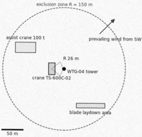
exclusion zone R = 150 m
OCR confidence: 0.97

assist crane 100 t
OCR confidence: 0.74

prevailing wind from SW
OCR confidence: 0.99

R 26 m
OCR confidence: 0.99

WTG-04 tower
OCR confidence: 0.98

crane TS-600C-02
OCR confidence: 0.97

blade laydown area
OCR confidence: 0.72

50 m
OCR confidence: 0.91

1. Pre-lift meeting; PTW signed by both parties.
OCR confidence: 0.99

2. Rotor locked with blade B pointing down; pitch system isolated.
OCR confidence: 0.93

3. Blade yoke fitted and load test at 0.5 m above the laydown area.
OCR confidence: 0.96

4. Blade B unbolted and lowered with both tag lines manned.
OCR confidence: 0.98

5. New blade lifted, bolted and torqued per Litware instruction.
OCR confidence: 0.98

6. Exclusion zone released only by the appointed person.
OCR confidence: 0.98

Prepared: Bram Okkerse, Appointed Person
OCR confidence: 1.00
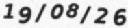
19/08/26
OCR confidence: 0.88

Approved: Dario Penwarden, O&M Supervisor
OCR confidence: 1.00

21/08/26
OCR confidence: 0.86
Figure f01
Generated description — written by a model from the figure image; not verified against the source.
A simple site-plan diagram shows a dashed circular exclusion zone labeled “R = 150 m” with an arrow indicating “prevailing wind from SW.” Inside the circle are labeled rectangular areas for an “assist crane 100 t,” a “crane TS-600C-02” near a marked “WTG-04 tower” point with “R 26 m,” and a “blade laydown area” near the bottom. A 50 m scale bar appears at the lower left.