Source page: Gearbox Fundamentals for Wind Technicians · Original file: original.pptx · Provenance: ✓ quote verified (native text) · Figures: generated description (model output, not verified)
Text
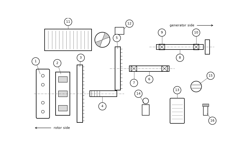
Exploded view of the FGT-3200
Item numbers as in the maintenance manual LWS-MM-GBX-32, figure 4-1.
Figure f02
Generated description — written by a model from the figure image; not verified against the source.
A schematic technical diagram of a machine assembly with multiple numbered parts labeled 1 through 16. It shows several rectangular and cylindrical components, dashed centerlines, and arrows indicating “rotor side” on the left and “generator side” on the right, with the numbered callouts pointing to individual elements such as plates, shafts, blocks, and a circular disc.